JHDL 0.2
JHDL 0.2
| JHDL Doc Home Page | User's Manual Home Page | << | < | > | >>
To create a state machine, you create two files - a JHDL object and a text file containing your machine's transition table.
Let's do a parity generator as an example. First, create a JHDL module which extends Fsm. Here is an example:
  /* File:   parity.java
             An even parity generator.
  */
  import byucc.jhdl.base.*;
  import byucc.jhdl.Fsm.*;
  public class parity extends Fsm
  {
    public static CellInterface[] cell_interface = {
      in("reset", 1 ),
      in("inData", 1 ),
      out("outData", 1 )
    };

    // Constructor
    public parity (Node parent, Wire reset, Wire inData, Wire outData) {
      super (parent, "parityGenerator");
      connect ("reset", reset);
      connect ("inData", inData);
      connect ("outData", outData);
      //
      // Do the actual Fsm construction
      buildFsm("parity.fsm");
    }
  }
Note that it has a constructor and interface like any other JHDL cell. Also note that the body of the constructor contains a single method call to
buildFsm("parity.fsm");
Next, create the file "parity.fsm" - it contains a transition table description of your state machine logic. An example of the file for our parity generator is shown below. It takes two inputs: a reset and a data input. It generates a single output which represents even parity.
  .inputs reset inData;
  .outputs outData;
  .states even odd;
  .encodings default;
  1-  -   even 0;   // When reset is true, reset to state "even"
  00 even even 0;
  01 even odd  0;
  00 odd  odd  1;   // A transition with a Mealy output
  01 odd  even 1;   // A transition with a Mealy output
A number of observations are in order:
  .inputs a b c d;
  .outputs x y z w q;
  .states s1 s2 s3 s4;
  1-.-- -  s1 1.101.0;
  00.10 s1 s2 0.011.0;
  00.1- s2 s3 1.000.1;
  --.00 s3 s4 0.111.1;
  --.-1 s4 s1 1.010.0;
Periods (".") are ignored by the parser and thus may be used to group inputs and outputs into columns.
The best way to understand the semantics of the transition table is to understand how the translation to gates is done. First, an AND gate is formed for each row of the table. The outputs of these AND gates are fed into a series of OR gates. Thus, one should be able to easily trace out the logic formed for a state machine by using the Schematic Viewer to view the AND/OR gate network created.
  .inputs reset inData;
  .outputs outData;
  .states even odd;
  .encodings default;
  1-  -   even 0;
  00 even even 0;
  01 even odd  0;
  00 odd  odd  0;
  01 odd  even 0;
  -- odd   -   1;   // This is a Moore output - it depends only on
		    // current state and not on any inputs.
Note how the next state in the last row is a don't care (-). This implies that the last row is only forming outputs and will not affect the next-state behavior of the machine.
At first glance, it may seem that the last three rows in this table contradict one another. The next to the last row states that a current state of "odd" and a low input result in a next state of "odd" and a low output. The last one implies that a current state of "odd" always results in a high output. Isn't this an output conflict? The answer is no. Output columns are the OR of all the rows that affect them (rows with a '1' in the colum). In this example, the last row is the only row which has any effect on the output.
No logic minimization is currently done on FSM descriptions - what you code up is what you get in terms of AND and OR gates. Thus, this second description will result in less gate level logic than the first. This may result in a smaller circuit after mapping to LUT-based FPGA logic.
.encodings "010" "111";
This would force a specific encoding. A third option would be:
.encodings onehot;
Here, a one-hot encoding is requested resulting in the following encoding: even="10", odd="01". The effect of one hot encoding is to reduce the width of the input forming logic since only a single bit need be checked for any given state transition.
  1- Fred Wilma   0;   // The don't care covers all states.
  00 Fred Barney  0;
It violates the "collectively exhaustive" property in that input combination "01" is not covered for this state.
The second property checked is called "mutually exclusive" and deals with whether the conditions on two different arcs leaving a given state can ever be true at the same time. Consider this trivial machine fragment:
  00 Fred Wilma   0;
  00 Fred Barney  0;
Note how condition "00" causes the machine to try to go to two different states at the same time. While this is a trivial example, more complex ones involving don't care conditions can be hard to find without the synthesizer's help. If either property is violated, an exception with a detailed error message will be thrown at build time.
   .inputs a b cin;
   .outputs cout s;
   001  01;
   010  01;
   011  10;
   100  01;
   101  10;
   110  10;
   111  11;
Only gates will be generated from this description.
  0 odd  odd  1;
  1 odd  even 1;
In this fragment, the output is asserted in state "odd" regardless of the input. A logic minimizer would make the output conditional only upon the current state. However, without logic optimization, the output signal is the OR of the 2 row conditions shown and will be dependent on the input. In systems with FSM's and datapath elements this has led to the creation of combinational logic loops - something the simulator will throw an error message for. If you must have an output with no dependence on the inputs you would code the machine with Moore outputs as described above in the section titled "Mealy and Moore Machines".
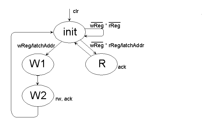
It accepts read and write requests and performs a number of functions:
The following files can be used to reproduce this design for demonstration purposes:
The output of a sample run is given below. The output produced includes a description of the state encodings performed, a reprocessed version of the transition table, and simulation output.
  fsmMemCtl Test
  Parsing description in file fsmMemCtl.fsm
  Assigning encoding using default numbering.
    Using an encoding length of 2.
  Done parsing, checking data structures...
  StateWidth = 2
  OneHot = false
  InputNames =  reset writereq readreq
  OutputNames =  latchaddr rw_ ack
  StateNames =  init w1 w2 r
  StateEncodings =  00 01 10 11
  TruthTable =
  1-- -(--) init(00) 010
  000 init(00) init(00) 010
  001 init(00) r(11) 110
  01- init(00) w1(01) 110
  0-- r(11) init(00) 011
  0-- w1(01) w2(10) 010
  0-- w2(10) init(00) 001
  Everything is built....
  In propagate manager init.
  Topological sort of circuit graph: started.
  Topological sort of circuit graph: finished.
  Building clock list.
  Simulation check: started.
  Simulation check: finished.
  100 010
  100 010
  000 010
  010 110
  000 010
  000 001
  000 010
  011 110
  000 010
  000 001
  000 010
  000 010
  001 110
  000 011
  000 010
  **** Simulation OK ****
| JHDL Doc Home Page | User's Manual Home Page | << | < | > | >>
Copyright (c) 1998-1999 Brigham Young University. All
rights reserved.
Reproduction in whole or in part in any form or
medium without express permission of Brigham Young University is
prohibited.