JHDL 0.2
JHDL 0.2
| JHDL Doc Home Page | User's Manual Home Page | << | < | > | >>
The Logic class provides a platform-independent API for instantiating standard FPGA gates and wires. The Logic API creates 7 basic types of objects:
Also, the Logic class provides a special placement API for specifying the technology mapping and placement of your cells. The Logic API is huge, with over 270 method calls defined at the present and growing! This is to allow the user the maximum flexibility possible in constructing a circuit. Before delving into all the details of the API, it will help you to understand a few basic rules and conventions that the Logic API follows. Understanding these basic rules will help you avoid referring to the documentation to find every function. Also, you will want to understand the nature of the TechMapper class in order to understand how the Logic methods get implemented in your target FPGA architecture.
_o suffix distinguishes methods that accept
output wires as parameters from those that create new wires for
the outputs.
_o suffix distiguishes how output wires are handled.
Wire cout = or( and(a,b), and(a,ci), and(b,ci) );
because the and() methods create the 2-input and gates
with a new wire attached to the output and return the new wire. This
nested form of gate instantiation can make your structural design very
clean and readable; in fact your structural code almost begins
to look behavioral.
Every basic Logic function has at least two versions: one which
creates a new wire as the output of the gate, and one which accepts
the output wire as a parameter. By convention, the latter case always
appends an _o suffix to the method name to indicate that
the output is supplied by the user. To be concrete,
Wire cout = or( and(a,b), and(a,ci), and(b,ci) );
creates new output wires for each of the gates instantiated, while
or_o( and_o(a, b, t1), and_o(a, ci, t2), and_o(b, ci, t3), cout );
implements precisely the same carry-out function but with
user-supplied wires as the outputs to all gates. Note that the
_o methods still return the output wire to allow for
nesting (i.e. t1,
t2, and t3 will be the return values of the
and_o() call, and cout will be the return value of
the or_o() call in the example above).
Note that some of the add()/sub()/addsub()
methods have two outputs (sum and carry-out); in these cases, the sum
wire is the return value of the method.
Most of the methods in the Logic API instantiate variable-width logic, based on the widths of the wires that are passed as parameters. For example, when we call
     Wire a = wire(8), b = wire(8), cin = wire(8);
     Wire cout = concat( wire(1), cin.range(7, 1) );
     or_o( and(a,b), and(a,ci), and(b,ci), cout );
we will get a full 8-bit carry chain. In this example, the
wire() calls create new wires; the concat() call creates
the carry-out bus as the right-shifted version of the carry-in bus.
Then, when we invoke the and() / or() methods, each of
these implement an 8-bit bitwise function, creating the carry chain
with a single JHDL statement. Generally, all Logic methods will do
similar things with arbitrary-width wires, allowing the JHDL designer
to rapidly build up parallel computational structures, but without
having to explicitly request the width of the block. All width
adaptation is automatic, based on the width of the wire parameters.
All Logic methods which instantiate gates allow you to pass an optional argument for naming the new gate and any output wires that are created. This String argument is always last in the parameter list. For example:
Wire cout = or( and(a,b), and(a,ci), and(b,ci), "carry_cell" );
will give the or gate the instance name "carry_cell". Also,
the returned wire will be named "carry_cell_o".
In general, you should be able to develop a "gut-feel" for the correct order of parameters in the Logic API. As with all of core JHDL, the Logic methods tend to have this parameter order:
     some_method( Cell parent, /* For static methods only */
		  Wire input0,
		  ...
		  Wire inputN,
		  Wire output0,
		  ...
		  Wire outputN,
                  int any_integer_arguments,
		  String name);
The Logic API defines methods to invoke and, or, and
xor-type boolean gates. These methods, combined with the
not operation, can be combined to implement any logic
function. The methods are overloaded to accept between 2 and 9 input
wires; thus and( a, b, c, d ); creates a 4-input
and gate while and( a, b ); creates a 2-input
and gate. Boolean gate methods with up to four inputs will
accept arbitrary-width wires; methods with five or more inputs only
accept 1-bit wires. This is primarily because we are lazy, and if
anyone has major issues with this we can extend the arbitrary-width
benefit to all boolean logic methods.
Also, each boolean gate type has a special 1-input-parameter version. For example,
     Wire a = wire(4);
     Wire f = and(a);
will build the function a[0] & a[1] & a[2] & a[3]. Thus
by concatenating bits into a single wire, the JHDL designer can get a
boolean function of any width. By contrast, if we do the
following:
     Wire a = wire(4);
     Wire b = wire(4);
     Wire f = and(a,b);
will build four parallel bitwise functions: f[0] = a[0] & b[0];
f[1] = a[1] & b[1]; f[2] = a[2] & b[2]; f[3] = a[3] & b[3].
The API also implements the boolean "not" function (i.e. an inverter) with the following:
     not(in);
     not_o(in, out);
The Logic API defines several methods to create flip-flops:
reg( d ) creates a default D flip-flop.
regc( d ) creates a globally, asynchronously cleared D
flip-flop .
regce( d, ce ) creates a globally, asynchronously
cleared, clock-enabled D flip-flop.
regp( d ) creates a globally, asynchronously preset D
flip-flop.
regpe( d, ce ) creates a globally, asynchronously
preset, clock-enabled D flip-flop.
The Logic API defines several methods to create wires:
wire() creates a wire of the "atomic" width of the
target architecture. "Atomic width" means the minimum width
wire allowed by the target architecture, i.e. 1 bit for XC4000, 4-bit for
HP-Chess, etc.
wire(String name) creates a named wire of the
default width of the target architecture.
wire(int width) creates a wire of the given width.
wire(int width, String name) creates a named wire of the
given width.
     Wire a = wire(3);
     Wire b = wire(4, "jomama");
creates a new 3-bit wire with a default name, and a new 4-bit wire with
name "jomama". In addition, each of these methods has a static
counterpart that accepts the parent Cell as the first parameter. This
allows new wires to be instantiated in an architecture-independent
manner, outside of the Logic class (most useful in test-benches,
etc.). This looks like:
Wire a = Logic.wire(this, 4);
This could be invoked from any class to create a new wire in a
platform-independent manner.
In addition to creating new wires, the Logic class will help you to manipulate wires in special ways:
concat(wire1, wire2, ..., wireN) concatenates the given
wire list into a single wire object. In this case,
wire1 would be the most significant bit(s) of the new
wire. The concat() method accepts from 1 to 16 wire
parameters of any width, and an optional name for the new wire.
nc() creates a special "dangling output" wire. This
wire cannot be connected to the input of any cell. It is completely
omitted in all netlisting. You can optionally specify the width of
the dangling wire if desired.
range(wire, int hi, int lo) returns the subrange
[hi:lo] from the given wire. Note that the same
functionality is performed by calling
wire.range(hi,lo); in this case, the method is part of
the Wire class, but again it does the same thing. The Wire version
of range() seems to be the slightly preferred version.
ashiftr(wire, int shift) performs the arithmetic right
shift of the wire.
shiftr(wire, int shift) performs the logical right
shift of the wire.
shiftl(wire, int shift) performs the logical left
shift of the wire.
_o version to
let you supply the output wire. As mentioned above, the range()
method can be used outside the Logic class by using the analogous
Wire.range() method. Similarly, the user can get concatenation
behavior outside the Logic class using the static versions of the
method:
Wire concatenation = Logic.concat(this, a, b, c, d, e, f);
Also, the same thing can usually be done using the constructors
provided by the wire class. This is a little trickier because the
exact wire class being used is generally platform-dependent (thus the
advantage of using the Logic class to hide this). But most Wire
classes should have constructors analogous to this one implemented by
Xwire, the Xilinx atomic wire class:
Wire concatention = new Xwire(this, a, b, c, d, e, f);
If for some reason the Logic API does not meet your specific needs for
creating wires, you should be able to get the desired results by
directly calling the constructor of your target-specific wire class.
In addition to the standard wire methods, the Logic API also provides methods for creating constant() wires, i.e., wires that need no (and will not allow) driver cells to be attached to them. These look like the following:
constant(int width, int value) creates a
width-bit wire with the given initialization value.
constant(int width, long value) does the same, but
uses a long to let you initialize up to 64-bit wires.
constant(int width, int[] value) does the same, but
uses an array of integers to let you initialize an
arbitrary-width constant.
Wire constant5 = Logic.constant(this, 8, 5);
Also, "_o" versions of constant exist so that the
user can drive a pre-created wire with the given constant value:
     public MyCell(Cell parent, Wire out1, Wire out2) {
       ...
       constant_o(out1, 5);
       constant_o(out1, 7);
     }
Finally, the user can explicitly insert a 1 bit "power" or "ground" symbol
with the vcc() and gnd() methods:
     vcc()
     vcc_o(Wire o)
     gnd()
     gnd_o(Wire o)
The Logic API provides method calls to instantiate basic adders and subtracters in the target architecture. These methods will optionally accept a carry-in and carry-out, if desired. Each of these methods returns the wire connected to the "sum" port of the adder / subtracter. The add() method has the following basic prototypes:
       add(a, b);
       add(a, b, ci);

       add_o(a, b, s);
       add_o(a, b, ci, s);
       add_o(a, b, ci, s, co);
Notice that the only way to get the carry-out signal is to use the
last add_o() method shown, explicitly providing the carry-out
wire yourself. And of course, each of these is further overloaded to
accept an optional String as the instance name of the adder. As
always, the exact implementation of adder is very platform-specific,
and is determined by the TechMapper class of
the corresponding platform. The user should generally expect the
layout of the adder to be predetermined by the TechMapper, using the
default style of the architecture. For example in the XC4000
architecture, this call would most likely result in a 2-bits-per-CLB,
north-to-south column layout. If more control of the adder layout is
desired, the user will need to use a platform-specific way of invoking
the adder.
The API for creating subtracters and adder-subtracters, via the
sub() and addsub() methods, is exactly analogous to the
add() API; the addsub() method includes the
add wire parameter just after ci, which
tells the circuit to add if high-asserted, or to subtract if
low-asserted.
All methods accept generic-width wires on the a, b, and
sum ports.
In the Logic class, basic memory cells can be invoked via the
ram() and rom() methods. For all methods, the initial
contents of the memory are specified with an array of
long values, such that index 0 of the array specifies the
initial contents of address 0 in the memory, and index 1 of the array
specifies the initial contents of address 1 in the memory, etc. The
Logic API currently limits you to a memory width of no
more than 64 bits. Because the exact implementation of memories is
very device specific, please consult the documentation on the
target-specific TechMapper class to see its inference rules on how to
instantiate memories.
The basic memory API is shown below; again, standard overloads exist to provide an instance name String.
     ram(din, we, addr, long[] init);
     ram_o(din, we, addr, o, long[] init);
     rom(addr, int width, long[] init);
     rom_o(addr, o, long[] init);
Widths of ram cells are determined from the width of the
din wire, and depth is determined by the width of the
addr wire. Width of rom cells is determined by the
width parameter for rom() calls and by the
o wire for rom_o() calls.
Note that there also exists a rams() API to implement a
synchronous-write RAM; its prototypes are identical to the
ram() API shown above.
The Logic API currently has two gate types that fall into the "miscellaneous" category: multiplexors and buffers:
     mux(d0, d1, sel);
     mux_o(d0, d1, sel, q);
     buf(in);
     buf_o(in, out);
The mux() call will implement a selection such that
d1 is selected if sel is high-asserted, else
d0. The buf() call instantiates a wire connection
buffer. This buffer does not correspond to actual hardware; it is
only used to connect two Wire objects. Again all methods optionally
accept a String instance name parameter, and self-adapt to the width
of the wires passed in.
The Logic class implements two basic methods for specifying technology-specific placement and mapping: place() and map(). The place method is used to set the relative position of a cell. Because the Logic API generally returns Wires from its cell-instantiating methods, place() will allow the user to "place" a Wire as well. The inference in this case is that we will place the cell that drives the given Wire. Thus, we can do the following:
     Wire out = and( a, b );
     place( out, 2, 5 );
allowing us to place the and gate, without ever getting an
explicit handle on the gate itself. The full placement API is given
below:
     place(Wire output, String s);
     place(Wire output, int x, int y);
     place(Wire output, int x, int y, String s);
     place(Wire output, int x, int y, int dx, int dy);
     place(Wire output, int x, int y, int dx, int dy, String s);
When the integer pair (x,y) is given, this coordinate value is used as
the placement constraint. When two integer pairs (x,y) and (dx,dy)
are given, an "iterated placement" is inferred to allow the user to
place multiple cells at once, in a regular layout. For example, say
that we call the following:
     Wire in = wire(8);
     Wire out = reg(in);
     place( out, 3, 4, 0, 1 );
Notice that this is exactly equivalent to the following:
     Wire in = wire(8);
     Wire out = reg(in);
     for (int i=0; i<8; i++)
       place( out.getWire(i), 3, 4+i);
which will instantiate an 8-bit register. The place() call will
attempt to line up the instantiated register in a single column,
starting at position (3,4). Assuming a 1-bit register granularity on
the target architecture, the out[0] register will be at
position (3,4), the out[1] register at (3,5), the
out[2] register at (3,6), ... Furthermore, the Logic
class defines the "magic number" MAX_PACK which can be used as
the dx or dy value in iterated placement. This magic number is
defined to mean, "pack in as many bits horizontally / vertically as is
allowed by the target architecture." For example, using
MAX_PACK as
the dy value for the XC4000 architecture tells the TechMapper to pack
two LUTs or two FFs per CLB.
Also, a String parameter can be passed which contains platform-specific directives that don't fit in the integer-pair syntax shown above. For example, this could be used to pass the ".F" or ".G" LUT-tags to the XC4000TechMapper to specify XC4000-specific placement.
The map() call implies the mapping of a logic function to a target-specific "atomic cell". The "atomic cell" would be LUTs and flip-flops for the XC4000 architecture, while it would be ALUs and flip-flops for the HP Chess architecture, etc. The map() call accepts a list of input wires and a single output wire; this list of wires implies the function that is to be mapped. For example, if we call:
     Wire out = or( and(a,b), and(a,ci), and(b,ci) );
     map( a, b, ci, out );
this implies mapping the function of the three and gates and
one or gate into a single LUT or ALU. The map() call
accepts from 2 to 9 input parameters, and optionally accepts a String
that gives target-specific constraints to the platform-specific
TechMapper.
It is critical to note that the Logic API defines absolutely nothing about the exact implementation of the map() and place() calls, beyond what has been specified here. The optional String arguments accepted by map() and place(), as well as the orientation of the (x,y) grid used for placement, are specifically "defined to be undefined" in the Logic class! They receive no interpretation in the Logic class, and are passed straight to the TechMapper for platform-specific interpretation.
The TechMapper class implements the exact Logic API for a given target FPGA architecture. The Logic class provides only an abstract definition of what transpires when its methods are called; the TechMapper class makes the final decisions as to how these methods are best implemented in its architecture. This is illustrated below:
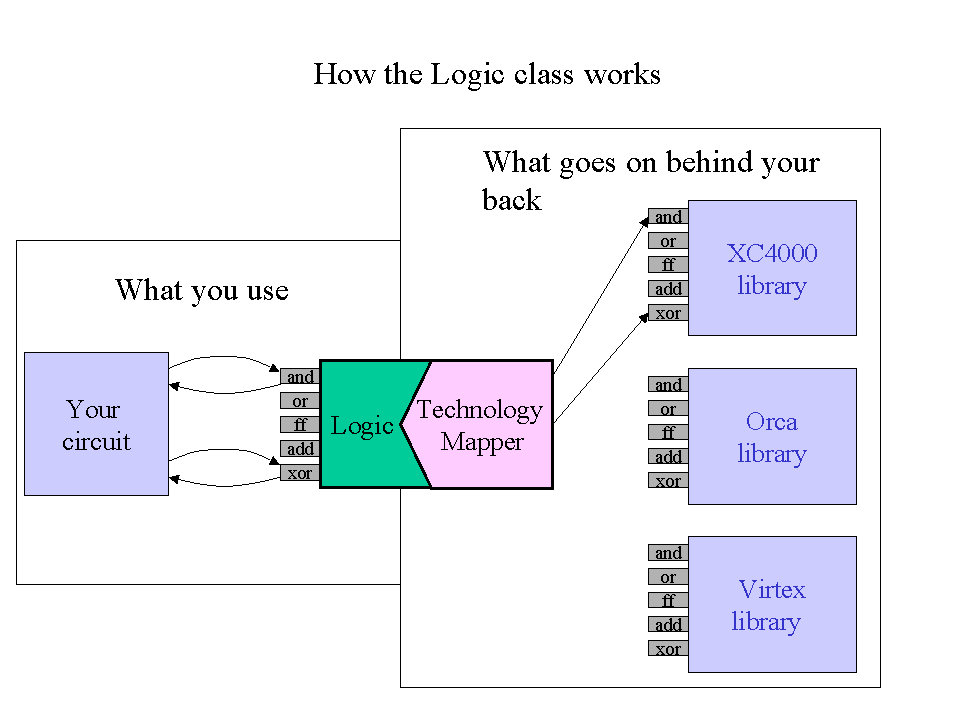
If the user does not select a TechMapper to target a specific library, Logic uses a generic cell library as default. These generic cells provide efficient simulation models but are not netlistable. To understand exactly what circuit gets implemented when you call Logic methods, you need to understand the TechMapper class that you are using. Currently, a TechMapper has only been developed for the XC4000 architecture. This class, the XC4000TechMapper, is discussed in the next section.
| JHDL Doc Home Page | User's Manual Home Page | << | < | > | >>

Copyright (c) 1998-1999 Brigham Young University. All
rights reserved.
Reproduction in whole or in part in any form or
medium without express permission of Brigham Young University is
prohibited.